
Page 47 - Solar Panels
P. 47
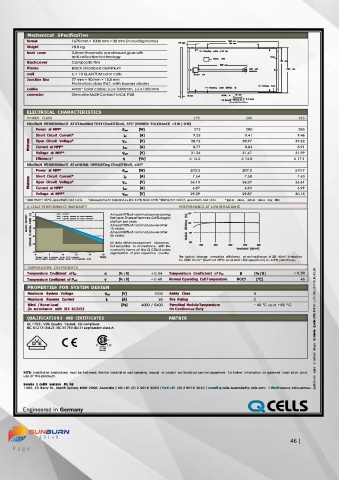
MechanIcal  SPecIfIcaTIon
           format         1670 mm × 1000 mm × 32 mm (including frame)      150  mm         1670  mm
                                                                                      980  mm
           Weight         18.8 kg

           front  cover   3.2 mm thermally pre-stressed glass with           6  ×  Grounding   points  ø  4.5  mm
                          anti-reflection technology                                            Frame
                                                                            Product   label
           Back cover     Composite film                                                           951  mm
                                                                              1000  mm

           frame          Black anodised aluminium                                      Cable  with   1000  mm
                                                                                        connectors
           cell           6 × 10 Q.ANTUM solar cells                 Junction   bo×

           Junction Box   77 mm × 90 mm × 15.8 mm
                          Protection class IP67, with bypass diodes
           cable          4 mm² Solar cable; (+) ≥ 1000 mm,  (-) ≥ 1000 mm           4  ×  Fastenin g   points  (DETAIL   A)   8  ×  Drainage  holes
           connector      Genuine Multi-Contact MC4, IP68            32  mm     DETAIL  A              16  mm
                                                                               24.5 mm   8.5 mm

           ELECTRICAL  CHARACTERISTICS                               275               280                285
           POWER  CLASS
           MInIMuM  PERfORMAnCE  AT STAndARd TEST COndITIOnS,  STC 1  (POWER TOLERAnCE +5 W /-0 W)
              Power  at MPP 2               P MPP   [W]              275               280                285
              Short  Circuit  Current*      I SC   [A]               9.35              9.41              9.46
           Minimum   Open  Circuit  Voltage*   V OC   [V]           38.72             38.97              39.22
                                                                                       8.84
                                                  [A]
                                                                     8.77
                                                                                                         8.91
              Current  at MPP*
                                            I MPP
              Voltage  at  MPP*             V MPP   [V]             31.36             31.67              31.99
              Efficienc y 2                 η     [%]               ≥ 16.5            ≥ 16.8            ≥ 17.1
           MInIMuM  PERfORMAnCE  AT nORMAL OPERATIng COndITIOnS,  nOC 3
              Power  at MPP 2               P MPP   [W]             203.3             207.0              210.7
                                                  [A]
              Short  Circuit  Current*
                                                                     7.54
                                                                                       7.58
                                                                                                         7.63
           Minimum   Open  Circuit  Voltage*   V OC   [V]           36.13             36.37              36.61
                                            I SC
                                                                     6.87
              Current  at MPP*
                                                                                                         6.99
                                                  [A]
                                                                                       6.93
                                            I MPP
              Voltage  at  MPP*             V MPP   [V]             29.59             29.87              30.15
          1 1000 W/m², 25 °C, spectrum AM  1.5 G   2  Measurement  tolerances STC ± 3 %; NOC ± 5 %  3  800 W/m², NOCT,  spectrum AM 1.5 G   * typic al  value s ,  actu al  valu e s  may  diffe r
           Q CELLS PERFORMANCE WARRANTY                         PERFORMANCE AT LOW IRRADIANCE
            1 0 0      Q CELLS          At least 97 % of nominal power during   110
           EFFICIENCY   [%]   POWER   97   I ndustry  standard  for  linear  warranties *   first year. Thereafter max. 0.6 % degra-   [%]   100
                       I ndustry  standard  for  tiered  warranties *
             95
                                        dation per year.
           RELATIVE   TO  NOMINAL   90   At least 92 % of nominal power after   EfficiENcy   90
                                        10 years.
                                        At least 83 % of nominal power after
                                        25 years.
            COMPARED   85               All data within measurement  tolerances.   rElaTivE   80
             80                         Full warranties  in  accordanc e  with  the   200   400   600   800   1000
             75                         warranty terms of the Q CELLS sales         irradiaNcE  [W/m²]
                                        organisatio n  of  your  respectiv e  country.
                           15
                  5
                       10
                                     25
             0  * Standard  terms  of  guarantee  for  the  10  PV  companies   20   YEARS   The  typical  change  in module  efficiency  at an irradiance  of 200  W/m²  in relation
             with  the  highest  production  capacity  in 2014  (as at:  September  2014)
                                                                to 1000 W/m² (both at 25 °C and AM 1.5 G spectrum) is -2.5 % (relative).

           TEMPERATURE  COEFFICIENTS
           Temperature  Coefficient  of I SC   α   [%  / K]   + 0.04   Temperatu re  Coeffic ien t  of V OC   β   [% / K]   − 0.29
           Temperature Coefficient  of P MPP   γ   [%  / K]   − 0.40   Normal Operating  Cell Temperature   NOCT   [°C]   45
           PROPERTIES  FOR SYSTEM  DESIGN
           Maximu m  System  Voltage   V SYS   [V]     1000   Safety  Class               II
           Maximu m  Reverse  Current   I R   [A]        20   Fire  Rating                C                     Q  cells  Q.PLUS- B F R- G4.1_275- 285_ 2016- 09_Re v 03_AU
           Wind  / Snow Load                [Pa]   4000 / 5400   Permitted Module Temperature   − 40  °C  up to +85  °C
           (in  accordance  with  IEC  61215)                On Continuous Duty

           QUALIFIC ATION S  AND  CERTIFICATES              PARTNER
          UL 1703; VDE Quality  Tested; CE-compliant;
          IEC 61215 (Ed.2); IEC 61730 (Ed.1) application class A
                                                                                                                ©  Hanwha
                                    Certified                                                                   change s
                                    UL  1703
                                    (254141)
                                                                                                                to  technica l


         NOTE:  Install ation  i nstructions  must  be foll owed. See the i nstallati on and operating  manual  or contact  our technical servi ce department  for further  information  on approved installation  and   subje ct
         use of this product.
                                                                                                                Specifications
         hanwha  Q  cellS  australia  Pty ltd
         1402, 20 Berry St.,  North Sydney NSW 2060, Australia  | tel +61 (0) 2 9016 3033 | FaX +61 (0) 2 9016 3032 | email q-cells-australia@q-cells.com  | WeB www.q-cells.com.au


                                                                                                                                                                                     46 |
     P a g e