
Page 45 - Solar Panels
P. 45
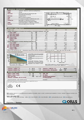
MECHANICAL  SPECIFICATION
            Format          1670 mm × 1000 mm × 32 mm (including frame)
            Weight          18.8 kg                                              1670  mm
                                                                150  mm                      980  mm              345  mm
            Front Cover     3.2 mm thermally pre-stressed glass with
                            anti-reflection technology                   6  ×  Grounding   points  ø  4.5  mm

            Back  Cover     Composite film                                                     Frame
                                                                            Product   label
            Frame           Black anodised aluminium                                                 951  mm
                                                                              1000  mm
            Cell            6 × 10 monocrystalline Q.ANTUM solar cells                  Cable  with   1000  mm
                                                                                        connectors
            Junction box    66-77 mm × 111-90 mm × 15-19 mm             Junction  bo×
                            Protection class IP67, with bypass diodes

            Cable           4 mm² Solar cable; (+) 1000 mm, (-) 1000 mm
                                                                                           8  ×  Drainage  holes
            Connector       Genuine Multi-Contact MC4, IP68                4  ×  Fastenin g   points  (DETAIL   A)

                                                                   32  mm      DETAIL  A             16  mm

            ELECTRIC AL  CHARAC TERISTICS
            POWER  CLASS                                          290          295           300           305
            MInIMuM  PERfORMAnCE  AT STAndARd TEST COndITIOnS,  STC 1  (POWER TOLERAnCE +5 W / -0 W)
               Power  at MPP 2               P MPP   [W]          290           295          300           305
               Short  Circuit  Current*       I SC   [A]         9.63          9.70          9.77          9.84
             Minimum   Open  Circuit  Voltage*   V OC   [V]      39.19         39.48        39.76         40.05
                                                                                             9.26
               Current  at MPP*
                                                                               9.17
                                                                 9.07
                                                    [A]
                                                                                                           9.35
                                              I MPP
               Voltage  at  MPP*             V MPP   [V]         31.96         32.19        32.41         32.62
               Efficienc y 2                  η    [%]          ≥ 17.4        ≥ 17.7        ≥ 18.0        ≥ 18.3
            MInIMuM  PERfORMAnCE  AT nORMAL OPERATIng COndITIOnS,  nOC 3
               Power  at MPP 2               P MPP   [W]         214.4        218.1         221.8         225.5
                                                                               7.82
                                                                                                           7.94
               Short  Circuit  Current*
                                                                                             7.88
                                                    [A]
                                                                 7.77
             Minimum   Open  Circuit  Voltage*   V OC   [V]      36.65        36.92         37.19         37.46
                                              I SC
                                                                                                           7.35
                                                                               7.20
                                                                                             7.27
               Current  at MPP*
                                                                 7.12
                                                    [A]
                                              I MPP
               Voltage  at  MPP*             V MPP   [V]         30.12        30.30         30.49         30.67
           1 1000 W/m², 25 °C, spectrum AM  1.5 G   2  Measurement  tolerances STC ± 3 %; NOC ± 5 %  3  800 W/m², NOCT, spectrum AM  1.5 G   * typic al  value s ,  actu al  valu e s  may  diffe r
            Q CELLS PERFORMANCE WARRANTY                         PERFORMANCE AT LOW IRRADIANCE
              1 0 0     Q CELLS          At least 98 % of nominal power during   110
            EFFICIENCY   [%]   POWER     98   I ndustry  standard  for  linear  warranties *   first year. Thereafter max. 0.6 % degra-   [%]   100

                        I ndustry  standard  for  tiered  warranties *
                                         dation per year.
              95
            RELATIVE   TO  NOMINAL   90   At least 92.6 % of nominal power up to   efficiency   relative   90
                                         10 years.
                                         At least 83.6 % of nominal power up to
                                         25 years.
             COMPARED   85               All data within measurement  tolerances.   80
              80                         Full warranties  in  accordanc e  with  the   200   400   600   800   1000
              75                         warranty terms of the Q CELLS sales         irradiance  [W/m 2 ]
                                         organisatio n  of  your  respectiv e  country.
                        10
                    5
                                      25
                             15
               0  * Standard  terms  of  guarantee  for  the  10  PV  companies   20   YEARS   Typical  module  performan c e  under  low  irradiance  conditions  in
                                                                 comparison to STC conditions (25 °C, 1000 W/m 2 ).
               with  the  highest  production  capacity  in 2014  (as at:  September  2014)

            TEMPERATURE COEFFICIENTS                   + 0.04
            Temperature  Coefficient  of I SC   α   [%  / K]   Temperatu re  Coeffic ient  of V OC   β   [% / K]   − 0.28
            Temperature Coefficient  of P MPP    γ   [%  / K]   − 0.39   Normal Operating  Cell Temperature   NOCT   [°C]   45
            PROPERTIES  FOR SYSTEM  DESIGN
            Maximu m  System  Voltage      V SYS   [V]   1000   Safety  Class              II
            Maximu m  Reverse  Current     I R   [A]      20   Fire  Rating                C                     Q Cells  Q.PEAK- G4 .1 _2 90- 30 5 _20 16- 09 _Rev0 1 _A U
            Wind  / Snow Load                  [Pa]   4000 / 5400   Permitted Module Temperature   -40 °C up to  +85 °C
            (Test-load  in accordance  with  IEC  61215)      On Continuous Duty

            QUALIFIC ATION S  AND  CERTIFICATES               PARTNER
            VDE Quality Tested, IEC 61215 (Ed. 2); IEC 61730 (Ed. 1), Application class A
            This data sheet complies with DIN EN 50380.
                                                                                                                 ©  Hanwha
                                                                                                                 changes
                                                                                                                  to  technical

                                                                                                                 subject
           NOTE:  Install ation  i nstructions  must  be foll owed. See the i nstallati on and operating  manual  or contact  our technical servi ce department  for further  information  on approved installation  and
           use of this product.
                                                                                                                 Specifications
           Hanwha  Q  Cells  Australia  Pty ltd
           1402,  20  Berry  St.,  North  Sydney  NSW  2060,  Australia  | Tel  +61 (0) 2 90163033  | FAX  +61 (0) 2 90163032  | eMAIl  q-cells-australia @q-c ells.com  | WeB  www.q-cells.com.au


                                                                                                                                                                                     44 |
     P a g e