Page 43 - Solar Panels
P. 43

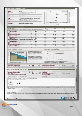
MECHANICAL SPECIFICATION
             Format         1685 mm × 1000 mm × 32 mm (including frame)            1685mm
                                                                                  980mm             352.5mm
             Weight         18.7 kg
             Front Cover    3.2 mm thermally pre-stressed glass with
                            anti-reflection technology
                                                                                                Frame
             Back Cover     Composite film

                                                                                                   951mm
             Frame          Black anodised aluminium
                                                                                                     1000 mm
             Cell           6 × 20 monocrystalline Q.ANTUM solar half cells
             Junction box   70-85 mm × 50-70 mm × 13-21 mm
                            Protection class IP67, with bypass diodes
             Cable          4 mm² Solar cable; (+) 1100 mm, (−) 1100 mm      4 × Mounting slots (DETAIL A)   8 × Drainage holes
             Connector      Multi-Contact, MC4, IP65 and IP68
                                                                   32mm        DETAIL A   16 mm
                                                                                        8.5mm
                                                                               24.5mm
             ELECTRICAL CHARACTERISTICS
             POWER CLASS                                          315           320          325           330
             MINIMUM PERFORMANCE AT STANDARD TEST CONDITIONS, STC 1  (POWER TOLERANCE +5 W / −0 W)
                Power at MPP 2                P MPP   [W]         315           320          325           330
                Short Circuit Current*        I SC   [A]         10.04        10.09         10.14        10.20
              Minimum   Open Circuit Voltage*   V OC   [V]       39.87        40.13         40.40        40.66
                                                                               9.60
                                                    [A]
                                                                  9.55
                                                                                                          9.71
                Current at MPP*
                                                                                             9.66
                                              I MPP
                Voltage at MPP*              V MPP   [V]         32.98        33.32         33.65        33.98
                Efficiency 2                  η     [%]         ≥ 18.7        ≥ 19.0        ≥ 19.3       ≥ 19.6
             MINIMUM PERFORMANCE AT NORMAL OPERATING CONDITIONS, NOC 3
                Power at MPP 2                P MPP   [W]        233.4        237.2         240.9        244.6
              Minimum   Short Circuit Current*   V OC   [A]      37.30        37.54         37.79        38.04
                                                                               8.14
                                                                 8.09
                                                                                             8.18
                                                                                                          8.22
                                              I SC
                                                    [V]
                Open Circuit Voltage*
                Current at MPP*               I MPP   [A]        7.51          7.56          7.60         7.64
                Voltage at MPP*              V MPP   [V]         31.07        31.39         31.70        32.01
            1 1000 W/m², 25 °C, spectrum AM 1.5 G   2  Measurement tolerances STC ± 3 %; NOC ± 5 %  3  800 W/m², NOCT, spectrum AM 1.5 G   * typical values, actual values may differ
             Q CELLS PERFORMANCE WARRANTY                         PERFORMANCE AT LOW IRRADIANCE
               100  98   Q CELLS          At least 98 % of nominal power during   110
             RELATIVE EFFICIENCY  COMPARED TO NOMINAL POWER [%]      95  90   Industry standard for tiered warranties *    degradation per year. At least 93.1 % of   RELATIVE EFFICIENCY [%]   100

                                          first year. Thereafter max. 0.54 %
                         Industry standard for linear warranties *
                                          nominal power up to 10 years. At least
                                          85 % of nominal power up to 25 years.
                                                                     90
                                          All data within measurement tolerances.


                                          warranty terms of the Q CELLS sales
                                          organisation of your respective country.
                                                                                        800
               85  80                     Full warranties in accordance with the   80     200   400     600     IRRADIANCE [W/M 2 ]  1000
               75                                                 Typical module performance under low irradiance conditions in
                                       25
                     5
                         10
                              15
                0  * Standard terms of guarantee for the 10 PV companies   20   YEARS   comparison to STC conditions (25 °C, 1000 W/m 2 ).
                with the highest production capacity in 2014 (as at: September 2014)
             TEMPERATURE COEFFICIENTS
             Temperature Coefficient of I SC   α   [% / K]   + 0.04   Temperature Coefficient of VOC   β   [% / K]   − 0.28
             Temperature Coefficient of P MPP    γ   [% / K]   − 0.37   Normal Operating Cell Temperature   NOCT   [°C]   45

             PROPERTIES FOR SYSTEM DESIGN
             Maximum System Voltage        V SYS   [V]   1000   Safety Class               II
             Maximum Reverse Current        IR   [A]      20   Fire Rating                 C
             Push / Pull Load                  [Pa]   5400 / 4000   Permitted Module Temperature   -40 °C up to +85 °C
             (Test-load in accordance with IEC 61215)         On Continuous Duty

             QUALIFICATIONS AND CERTIFICATES                  PARTNER
             VDE Quality Tested, IEC 61215 (Ed. 2); IEC 61730 (Ed. 1), Application class A
             This data sheet complies with DIN EN 50380.                                                         Specifications subject to technical changes © Hanwha Q CELLS Q.PEAK DUO-G5_315-330_2017-07_Rev01_EN

            NOTE: Installation instructions must be followed. See the installation and operating manual or contact our technical service department for further information on approved installation and
            use of this product.


            Hanwha Q CELLS GmbH
            Sonnenallee 17-21, 06766 Bitterfeld-Wolfen, Germany | TEL +49 (0)3494 66 99-23444 | FAX +49 (0)3494 66 99-23000 | EMAIL sales@q-cells.com | WEB www.q-cells.com


                                                                                                                                                                                     42 |
     P a g e
   38   39   40   41   42   43   44   45   46   47   48