
Page 25 - Solar Panels
P. 25
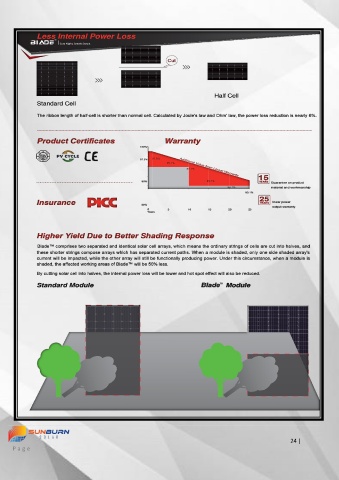
Less Internal Power Loss
 TM                 TM
 Blade™ – A Module  re-Modeled   Cuts Night, Breaks Dawn.
 Cuts Night, Breaks Dawn.


                                                            Cut
 Seraphim’s Blade™ Series solar module boasts two identical parts, which are composed of cells that are half the size of ordinary solar
 cells. By cutting cells into halves, these smaller currents will help reduce “Cell To Module” loss, which means higher output.
 In the meantime, the overall space between cells are doubled, and more light will be transferred into power through multiple reflections.
 Compared to mainstream standard modules, the Blade™ series module has lower current and series resistance which helps minimize
 mismatch loss, internal power loss, and shadow effect, etc. Once one cell has EL defect or appearance defect, such as black edge or V
 sharp. After cutting, one intact half can be reused.                       Half Cell
              Standard Cell

 More Output   Higher Efficiency   Higher ROI   The ribbon length of half-cell is shorter than normal cell. Calculated by Joule's law and Ohm' law, the power loss reduction is nearly 6%.


 Less Mismatch loss   Product Certificates                 Warranty
                                                  100%

 Instead of 6 internal strings of cells, the Blade series module has 2 x 6 shorter ones. This design effectively deals with the mismatch   97.5%   97.5%
                                                            95.1%
 happened between cells caused by shadow, out of sync performance degradation, ect.
                                                                   92.1%
                                                                                             15
                                                   90%                    89.1%             YEARS
 Standard Module   With 6 internal strings of cells                                             Guarantee on product
                                                                                 86.1%          material and workmanship

                                                                                       83.1%
                                                                                            25
              Insurance                                                                     YEARS   linear power
 9A   9A   9A   9A   9A    9A                      80%                                           output warranty
                                                     0      5      10     15     20     25
 9A   9A   9A   9A   9A    9A                        Years
 9A   9A   9A   9A   9A    9A
    9A   9A   9A   9A   9A    9A
 9A   9A   9A   9A   9A    9A
 9A   9A   9A   9A   9A    9A   Higher Yield Due to Better Shading Response
 9A   9A   9A   9A   9A    9A
          9A   9A   9A   9A   9A    9A    Blade™ comprises two separated and identical solar cell arrays, which means the ordinary strings of cells are cut into halves, and
 9A   9A   9A   9A   9A    9A
              these shorter strings compose arrays which has separated current paths. When a module is shaded, only one side shaded array's
 9A   9A   9A   9A   9A    9A
 9A   9A   9A   9A   9A    9A   current will be impacted, while the other array will still be functionally producing power. Under this circumstance, when a module is
              shaded, the affected working areas of Blade™ will be 50% less.
 9A    9A  9A    9A  9A     8.7A   By cutting solar cell into halves, the internal power loss will be lower and hot spot effect will also be reduced.

     Design Sketch          Circuit Diagram         Electrical Mismatch
              Standard Module                                           Blade Module
                                                                              TM

 Module current output is 8.7A, current mismatch in series is  0.3A.


 Blade™   With 2 x 6 internal strings of cells

 4  .5A   4.5  A  4.   5A   4.5 A  4.   5A   4.5  A


 4  .5A   4.5  A  4.   5A   4.5   A  4.   5A   4.5  A
 4  .5A   4.5  A  4.   5A   4.5   A  4.   5A   4.5  A
 .
 4 5A   4.5  A  4.   5A   4.5 A  4.   5A   4.5  A


 4  .5A   4.5  A  4.   5A   4.5 A  4.   5A   4.5  A


 4  .5A   4.5  A  4.   5A   4.5 A  4.   5A   4.5  A
 4  .5A   4.5  A  4.   5A   4.5 A  4.   5A   4.5  A


 4  .5A   4.5  A  4.   5A   4.5 A  4.   5A   4.5  A
 4  .5A   4.5  A  4.   5A   4.5 A  4.   5A   4.5  A

 4  .5A   4.5  A  4.   5A   4.5   A  4.   5A   4.5  A

 4  .5A   4.5  A  4.   5A   4.5 A  4.   5A   4.5  A
 4.5A 4.5A 4.5A 4.5A 4.5A 4.5A


       4  .5A   4.5  A  4.   5A  5A   4.5 4.5 A  4.   5A  5A   4.5  A  A

 4.5
 4.5
 4  .5A
 A  4.
 A  4.
 4  .5A   4.5  A  4.   5A   4.5   A  4.   5A   4.5  A

 .
 4 5A   4.5  A  4.   5A   4.5 A  4.   5A   4.5  A

 4  .5A   4.5  A  4.   5A   4.5   A  4.   5A   4.5  A
 4  .5A   4.5  A  4.   5A   4.5   A  4.   5A   4.5  A
 .
 4 5A   4.5  A  4.   5A   4.5 A  4.   5A   4.5  A


 4  .5A   4.5  A  4.   5A   4.5 A  4.   5A   4.5  A
 4  .5A   4.5  A  4.   5A   4.5 A  4.   5A   4.5  A

 .

 4 5A   4.5  A  4.   5A   4.5 A  4.   5A   4.5  A


 4  .5A   4.5  A  4.   5A   4.5 A  4.   5A   4.5  A
       4  .5A   4.5  A  4.   5A   4.5 A  4.   5A   4.35  A

     Design Sketch        Circuit Diagram       Electrical Mismatch
 Module current output is 4.5+4.35=8.85A, current mismatch in series is  0.15A.

                                                                                                                                                                                     24 |
     P a g e